* One common 'sink' point for all undesired and stray AC, DC and RF currents
* This point, with adequate wire, becomes THE path of least resistance
* No one chassis, source or event will create a potential difference between equipment
* This point is common-to but separate and away from operating position, antenna locations so the energy is not dissipated near people or equipment
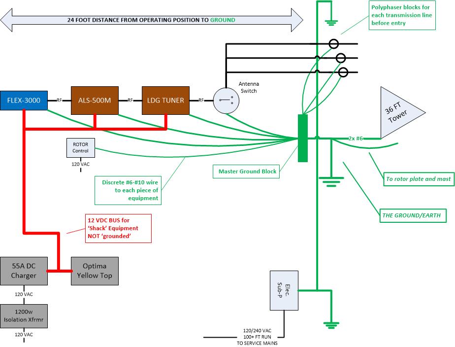
Implementing a single-point ground should be simple and obvious. ONE and only ONE point is used as the connection point for any and all ground wires run to/from any and all equipment. Multiple ground rods may contribute and connect to this single point, but connections are not made to the individual ground rods - ONLY to THE single determined ground point.
This method DOES use a lot more wire than the unsuitable, inadequate methods, but it is the only way to assure that undesired voltage/current events on any one piece of equipment do not affect the ground potential connection of other equipment.
Note - this indicates a single wire to/from each individual piece of equipment running all the way to the single ground point. This makes for a LOT of connection points, requiring a substantial set of terminal block options for multiple and various conductors. Stacking connections on single lugs and terminals is not advised.
The illustration of my station below depicts an all-12 VDC-powered setup. NONE of the 12 VDC system itself is at ground except where it meets a grounded load chassis. There are no ground-loops with the A.C. electrical system. Only the rotor control uses 120 VAC. For clarity the several VHF/UHF radios and their antenna lines are not shown, but they enjoy similar connection and ground discipline.
Indeed, NEC/NFPA requirements and local electrical codes should be heeded at all times, but none of that accounts for the many and various types of currents introduced by RF systems. Once you start extending an interior electrical connection, like a TV antenna, to an exterior environment, things change. That is why telephone lines as well as cable and satellite TV typically provide their own grounding blocks - additional points of diverting electrical intrusion to ground.
With the typically larger, taller and higher RF power of amateur (and commercial) radio systems, we present more opportunities for 'stray' electrical issues than any other situation.
While much of our equipment, as in a typical HF + AMP + TUNER configuration may appear to be tied together through the shield of coaxial cable jumpers, remember we're using that wire for our RF signal, and not all of us are using the biggest and best cable. Depending on one cable to do the work of others is not a wise choice. This also extends to the idea that you're using your coax to make up for poor or no ground in any other unit's power cable.
If the power cord for the tuner has a weak ground wire the next path is back to the transceiver through a piece of coax and then to ground through that power cord. Now three pieces of equipment are in harm's way!
Let's not stop there... add in the outlet strip and its cord, then the outlet, and the unknown path of the outlet's electrical ground wire through your house. At this point just imagine a huge burn pattern from your antenna all the way through your shack, around your house to your main electrical box. That's quite a mess!
Adding up the damage in the shack will be pretty depressing. Explaining the rest of this to the fire department, insurance company, your family, and the contractor bidding on repairing this... WOW!
You figured that ground on one chassis is pretty good, and why waste wire? Connect the next chassis to it, the next chassis to the next one, just like the RF connections.
In this case we end up with pretty much the same risk to other pieces of equipment for an event that happens to another. Depending on where the looping starts or ends dictates which pieces of equipment are put at the most or least risk for the others. Sacrificial ham gear huh?
Our objective is to not risk/sacrifice other items to events happening elsewhere - let EACH item have it's own ground diversion!
ALMOST-GROUND: Another thing not accounted for here is the capacity of that ground wire run in from the rod. If that wire is not large enough it will act like a resistor. Electrical events on other chassis will cause a rise in the 'ground' voltage of other chassis also putting them at risk. Not what we want. Each piece of equipment must have it's own wire running to THE single ground point.
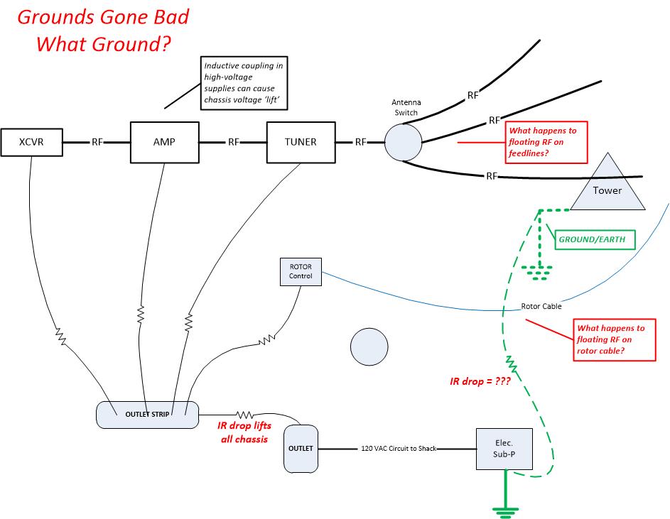
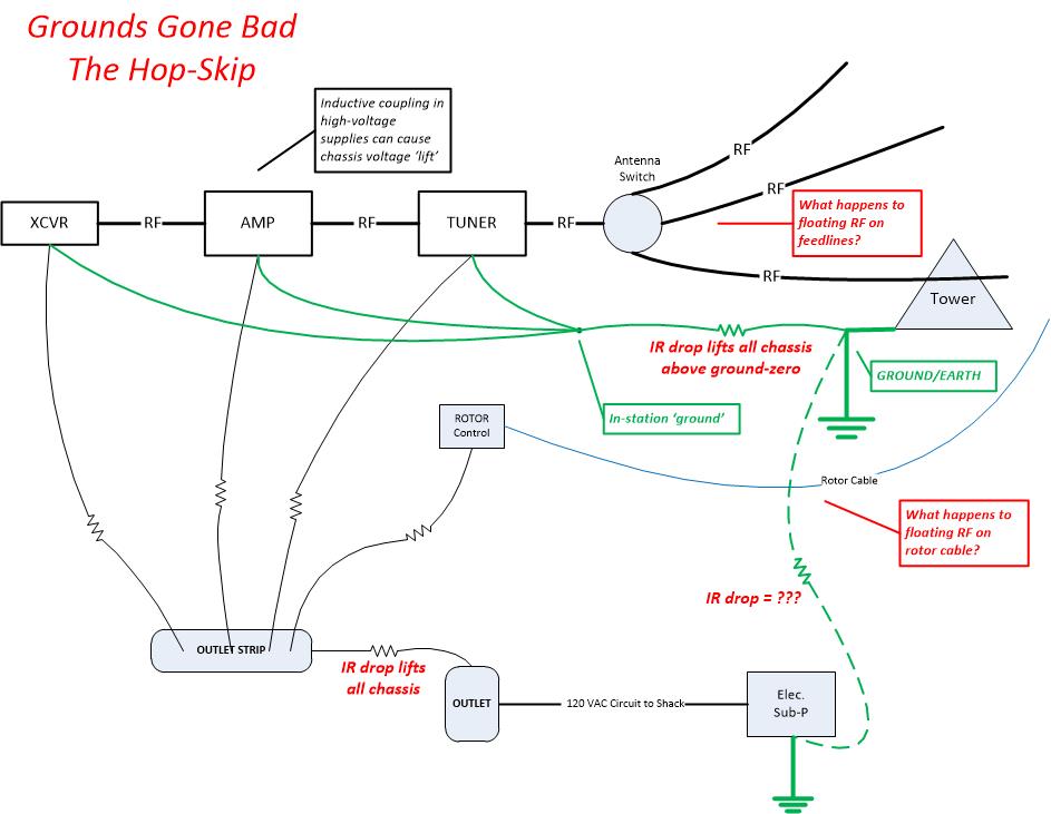
Did you notice the lack of ground-block for the antenna feedlines? Stray RF is coming right into the shack!
Did you also notice the potential for an electrical-vs.-station ground loop?

Again we lack external grounding for antenna lines so stray RF comes right into the shack and gear.
Another thing accommodated or not - a solid tie-in to the electrical mains ground point. DO NOT attach your ground wire to the electrical outlet box in the shack to cover for this mistake! This defeats that safety ground protection of the electrical system and would have any electrical safety event route to and through your shack, equipment and your ground rod rather than the intended path. The burn pattern discussed above in reverse...
ALMOST-GROUNDED: Again, sharing ground, worse letting the wrong things use ground or not have their own ground is just not what this is about. You risk creating different and worse problems than you might solve.
Mike Holt does Earth ground resistance tests
Mike is a bit 'animated' but has some terrific information about NEC/NFPA and electrical system grounds.
Motorola R56 at Repeater-Builder
Polyphaser - Solutions for Comm Sites
© 2015 de Jim Aspinwall, No1PC
Rights of referenced and linked material up to their respective authors/publishers/owners.
